お買い物ついでに、忘れないようDTR付のUSBシリアル変換をゲットしました。
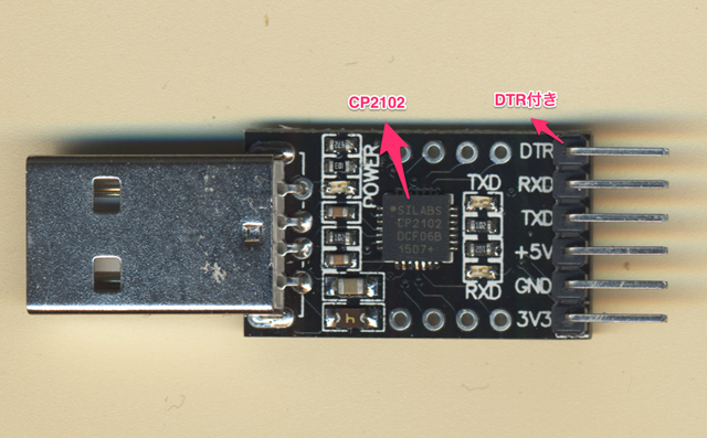
動作確認してみました。
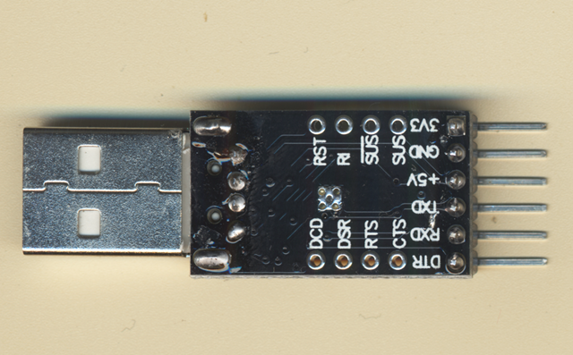
いやぁ、便利ですね。
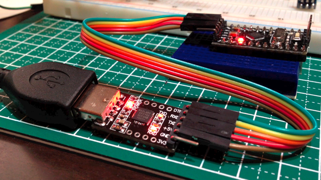
前のCP2102 は ESP8266 用にしてこっちは、ProMini用にします。
映像はこちら。
[youtube https://www.youtube.com/watch?v=xDVnZ8GZNqc]
ESP-12 モジュールがかなり気に入りました。ので、電源を考えるにあたり、正式なスペックを調査しました。
今までで最速で届いた、パーツです。5/1 に発注して9日に到着。このストアはすごくいいですね。
10個で買ったので、1個あたり97円です。
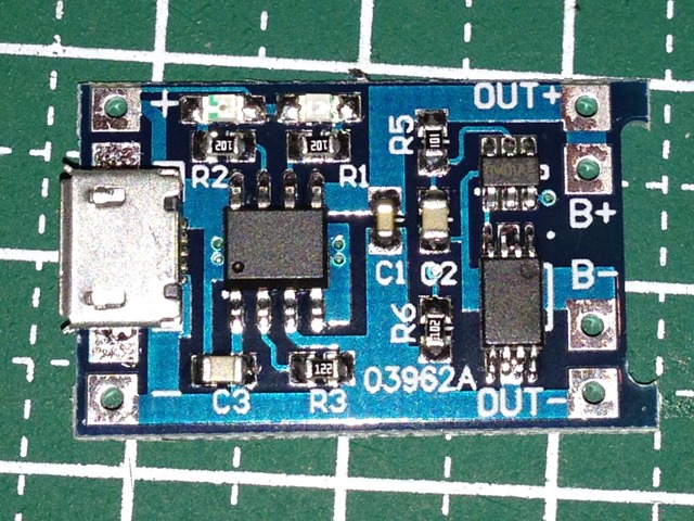
保護回路付で、よくできています。
メインのIDは、TP4056 でNanJing Top Power ASIC Corp製。保護回路に、DW01A と ML8205A が乗っています。
TP4056.pdf
http://dlnmh9ip6v2uc.cloudfront.net/datasheets/Prototyping/TP4056.pdf
DW01x-DS-17_EN.pdf
http://www.ic-fortune.com/upload/Download/DW01x-DS-17_EN.pdf
ML8205A
http://www.datasheet4u.com/datasheet/M/L/8/ML8205A-MEILAI.pdf.html
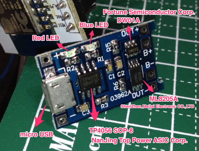
マイクロUSBから給電すると、ブルーLEDがつきます。電池がないと赤LEDは点滅する感じ。
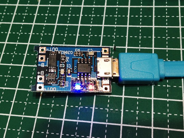
OUT側の内側は、バッテリーへ。OUT+- は出力へ。
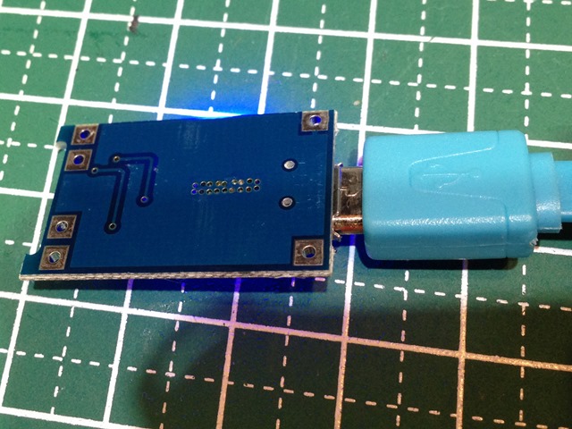
ジュリアンさんの解説映像がわかりやすいです。発音もいいですしね。
[youtube https://www.youtube.com/watch?v=Qw4psECqpwI]
IoTデバイス用にと思っていますが、まだ電池ボックスがないんですよね。あぁ、3Dプリンターがほしいぃ。
Aliexpress経由で購入した素材で遊びました。
20個で、98円のGL5528光センサーをつけてみました。
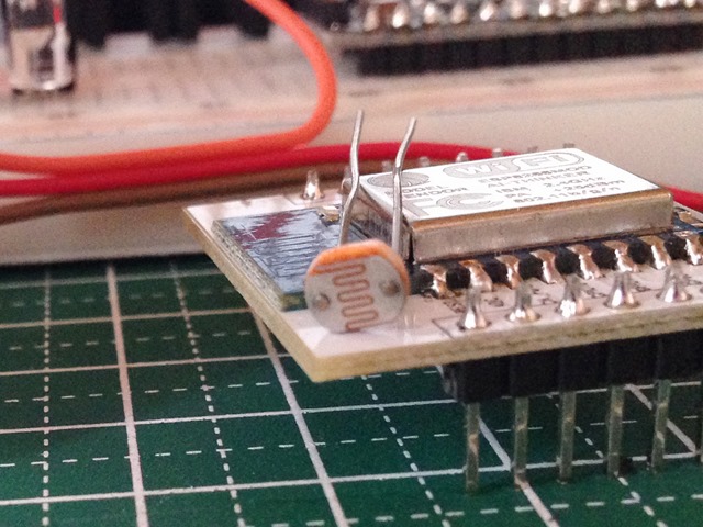
20個で98円ということは、1個あたり約5円ですね。
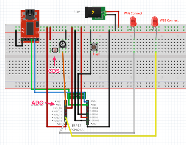
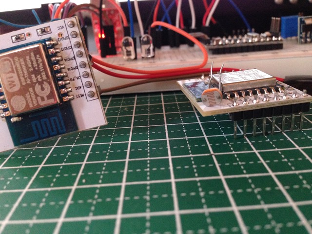
ADC にこんな感じでつけてみました。
当初ADC Pinにつけても値が拾えず、抵抗値を可変で調整したらうまく値が取れました。このADC-GND間の電圧は、強い光を当てた状態で約1.13Vくらいです。夜、電気をつけた状態で0.98Vくらい。手で覆うと0.6Vくらいになる感じです。
コードは以下のようです。エラー処理が抜けているのか、バグがあるのかわかりませんがちょっと不安定です。
/*
 ESP8266 HTTP get webclient.
 ADC Read test.
 https://thingspeak.com/channels/37124
 Arduino-compatible IDE with ESP8266
 arduino-1.6.1-macosx-java-latest-signed.zip
 https://github.com/esp8266/Arduino
 JunkHack 2015.05.09
 */

#include <ESP8266WiFi.h>

const char* ssid     = "JunkHack";
const char* password = "testtest";

const char* host = "184.106.153.149";

int WiFiConLed = 13;
int WEBconLed = 12;

void setup() {
  pinMode(WiFiConLed, OUTPUT);
  pinMode(WEBconLed, OUTPUT);
  Serial.begin(115200);
  delay(10);

  // We start by connecting to a WiFi network

  Serial.println();
  Serial.println();
  Serial.print("Connecting to ");
  Serial.println(ssid);

  WiFi.begin(ssid, password);

  while (WiFi.status() != WL_CONNECTED) {
    delay(500);
    Serial.print(".");
    digitalWrite(WiFiConLed, HIGH);
    delay(400);
    digitalWrite(WiFiConLed, LOW);
    delay(100);
  }

  Serial.println("");
  Serial.println("WiFi connected");
  Serial.println("IP address: ");
  Serial.println(WiFi.localIP());
}

int value = 0;
int count = 0;
int adc = 0;

void loop() {
  delay(5000);
  ++value;

  Serial.print("connecting to ");
  Serial.println(host);

  // Use WiFiClient class to create TCP connections
  WiFiClient client;
  const int httpPort = 80;
  if (!client.connect(host, httpPort)) {
    Serial.println("connection failed");
    return;
  }

  digitalWrite(WEBconLed, HIGH);
  delay(1000);
  count += 1;

  Serial.print("ADC: ");
  adc = analogRead(A0);
  Serial.println(adc);

  // We now create a URI for the request
  String url = "/update?key=5GPL7J7EVNB5R8GE&field1=";
  url += adc;
  Serial.print("Requesting URL: ");
  Serial.println(url);

  // This will send the request to the server
  client.print(String("GET ") + url + " HTTP/1.1\r\n" +
               "Host: " + host + "\r\n" +
               "Connection: close\r\n\r\n");
  delay(10);

  // Read all the lines of the reply from server and print them to Serial
  while(client.available()){
    String line = client.readStringUntil('\r');
    Serial.print(line);
  }

  // Close connection
  Serial.println();
  Serial.println("closing connection");
  digitalWrite(WEBconLed, LOW);
}
とりあえず、こんな感じで、データが投げられています。
単体でWifi に接続して、データをThingSpeak に投げるテストをしてみました。
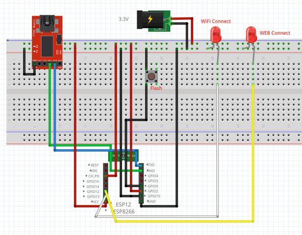
配線はこんな感じで、GPIO12 と 13 にLEDをくっ付けてみました。アクセスポイントにコネクションしたときにダブルブリンク、WEBにコネクションしているときは、点灯する感じです。
まだ、センサーとかはつけていないのでカウンター値を上げてみました。
コードはこんな感じです。
/*
 ESP8266 HTTP get webclient test.
 https://thingspeak.com/channels/37124
 Arduino-compatible IDE with ESP8266
 arduino-1.6.1-macosx-java-latest-signed.zip
 https://github.com/esp8266/Arduino
 JunkHack 2015.05.09
 */

#include <ESP8266WiFi.h>

const char* ssid     = "JunkHack";
const char* password = "testtest";

const char* host = "184.106.153.149";

void setup() {
  pinMode(13, OUTPUT);
  pinMode(12, OUTPUT);
  Serial.begin(115200);
  delay(10);

  // We start by connecting to a WiFi network

  Serial.println();
  Serial.println();
  Serial.print("Connecting to ");
  Serial.println(ssid);

  WiFi.begin(ssid, password);

  while (WiFi.status() != WL_CONNECTED) {
    delay(500);
    Serial.print(".");
    digitalWrite(13, HIGH);
    delay(400);
    digitalWrite(13, LOW);
    delay(100);
  }

  Serial.println("");
  Serial.println("WiFi connected");
  Serial.println("IP address: ");
  Serial.println(WiFi.localIP());
}

int value = 0;
int count = 0;

void loop() {
  delay(5000);
  ++value;

  Serial.print("connecting to ");
  Serial.println(host);

  // Use WiFiClient class to create TCP connections
  WiFiClient client;
  const int httpPort = 80;
  if (!client.connect(host, httpPort)) {
    Serial.println("connection failed");
    return;
  }

  digitalWrite(12, HIGH);
  delay(1000);
  count += 1;


  // We now create a URI for the request
  String url = "/update?key=5GPL7J7EVNB5R8GE&field1=";
  url += count;
  Serial.print("Requesting URL: ");
  Serial.println(url);

  // This will send the request to the server
  client.print(String("GET ") + url + " HTTP/1.1\r\n" +
               "Host: " + host + "\r\n" +
               "Connection: close\r\n\r\n");
  delay(10);

  // Read all the lines of the reply from server and print them to Serial
  while(client.available()){
    String line = client.readStringUntil('\r');
    Serial.print(line);
  }

  // Close connection
  Serial.println();
  Serial.println("closing connection");
  digitalWrite(12, LOW);
}
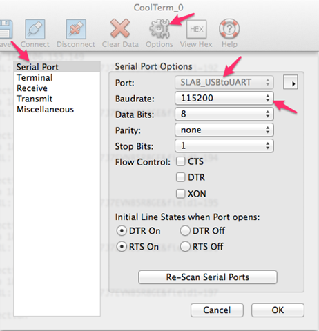
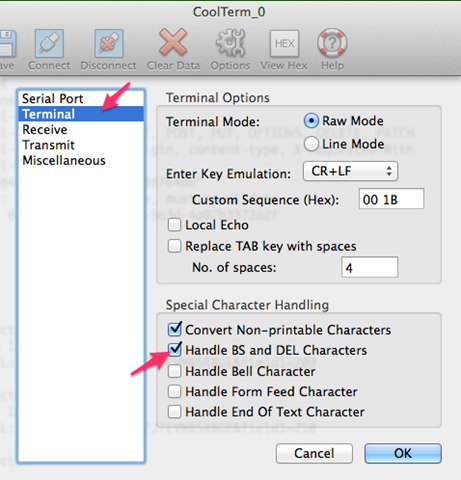
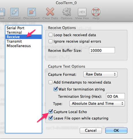
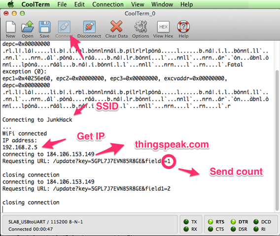
ArduinoIDE のシリアルモニターでも見れますが、osx のCoolTermでは以下のように見れます。
参考にさせて頂いたページ
ESP8266モジュールをArduinoとして使う
http://ehbtj.com/electronics/esp8266-as-arduino
ESP8266をUSB-TTLシリアル変換してWi-Fiの確認する
http://qiita.com/masato/items/a3b71f8a17b876be8f76
ESP8266 Wifi Temperature Logger
http://www.instructables.com/id/ESP8266-Wifi-Temperature-Logger/?lang=ja&ALLSTEPS
ESP8266 チップを使った WiFiモジュールの ESP-12 を触ってみました。
面白いことに、このモジュール単体でGPIOがあり、ArduinoIDEでプログラムを書き込みできてしまうという点です。
まずは、ハードウェアのHelloWorldであるLED点滅をやってみました。
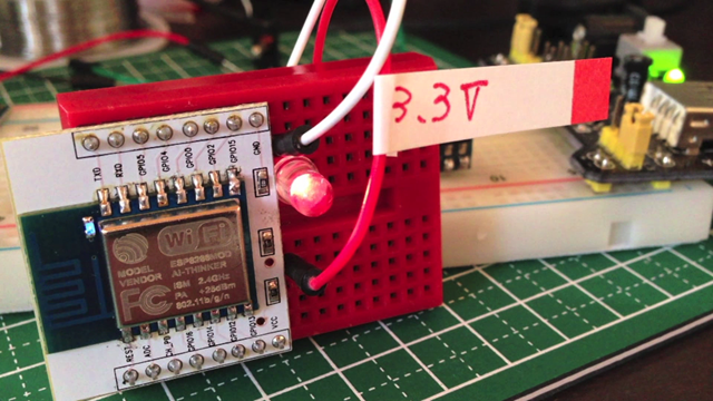
モジュールはこんな感じでちっこいです。3.3Vで動作します。ブレッドボードに刺さらない2mmピッチなので下駄を履かせています。 基盤のしたにジャンパーを伸ばしてやらないと配線できませぬ。
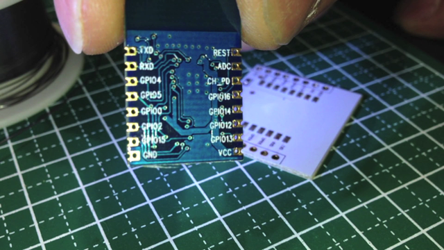
そのうち、オフィシャルのArduinoIDE にも入るかと思いますが、以下からESP8266 をサポートしたIDEをゲットします。
esp8266/Arduino · GitHub
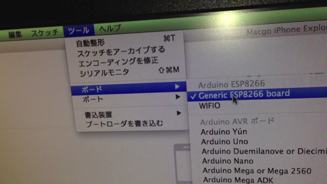
ボードにESP8266 が入っています。
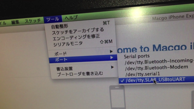
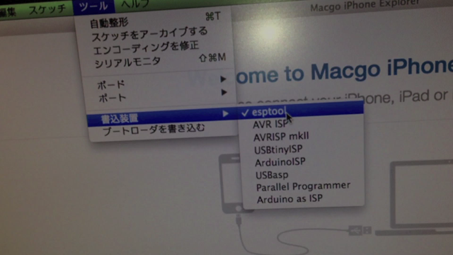
書き込み装置には、esptool が入っています。
配線は以下のようにします。上にあるのは、5V to 3V のレギュレーターです。書き込みするときは、GPIO0 をGND に落としてやります。
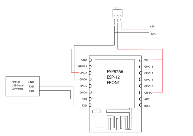
コードはダブルブリンクを以下のようにしてみました。
/*
 ESP8266 Double Blink Sample.
 Arduino-compatible IDE with ESP8266
 arduino-1.6.1-macosx-java-latest-signed.zip
 https://github.com/esp8266/Arduino
 JunkHack 2015.05.08
 */

void setup() {
  pinMode(0, OUTPUT);
}

void loop() {
  digitalWrite(0, HIGH);
  delay(400);
  digitalWrite(0, LOW);
  delay(100);
  digitalWrite(0, HIGH);
  delay(500);
  digitalWrite(0, LOW);
  delay(1000);
}
IDE から書き込みすると以下のようになります。
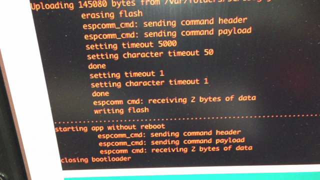
とりあえず、書き込み方法はわかりました。
映像は以下をどうぞ。
[youtube https://www.youtube.com/watch?v=9TUboOLnz6A]
次回は、WiFi でコネクションする何かをやりたいですね。
面白いことに、透過モードにするファームウェアもあるので試してみたいですね。
ESP8266-transparent-bridge
https://github.com/beckdac/ESP8266-transparent-bridge
nWorld ESP8266で透過モードを使ってみた。
|
|