もう1月も終わりですね。なんだか速く月日が経つような気がします。
さて、今日は 先日作った INA226 の電流電圧センサーを I2C で arduino nano クローンにて計測してみました。
前回の調査で見つけた、ポーランドのサイトにいいチュートリアルがありました。
Korneliusz Jarzębskiのサイト
Dwukierunkowy cyfrowy czujnik prądu/mocy INA226github
Arduino-INA226
https://github.com/jarzebski/Arduino-INA226
このGitHub のsimple のソースにライブラリを配置し、
./INA226_simple
├── INA226.cpp
├── INA226.h
└── INA226_simple.ino
INA226.cpp の記述を以下に変更。25mR のシャント抵抗の設定をします。
#include "INA226.h"
::
void setup()
{
::
  // Calibrate INA226. Rshunt = 0.025 ohm, Max excepted current = 4A
  ina.calibrate(0.025, 1);
::
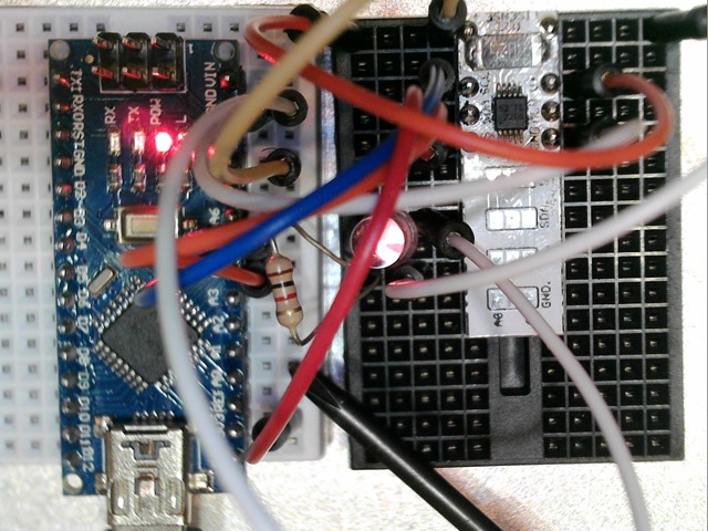
配線は以下のようにしました。ちょっとわかりにくいですが、Arduino の A5(SCL) と A4(SDA) をつないで、GND と 3.3V を VSS に入れます。あとは、負荷を電流計測にハイサイド側に付ける感じです。
シリアル通信を開くと、以下のようになっています。
Initialize INA226
-----------------------------------------------
Mode:                  Shunt and Bus, Continuous
Samples average:       1 sample
Bus conversion time:   1.100ms
Shunt conversion time: 1.100ms
Max possible current:  3.28 A
Max current:           3.28 A
Max shunt voltage:     0.08 V
Max power:             117.96 W
-----------------------------------------------
Bus voltage:   4.67875 V
Bus power:     0.01250 W
Shunt voltage: 0.00007 V
Shunt current: 0.00300 A

Bus voltage:   4.68125 V
Bus power:     0.01250 W
Shunt voltage: 0.00007 V
Shunt current: 0.00300 A

Bus voltage:   4.67750 V
Bus power:     0.01250 W
Shunt voltage: 0.00007 V
Shunt current: 0.00300 A
PC からのUSB 電圧は4.67V 程度のようです。3mA で12.5mW ということがわかりました。ちゃんと計測できているようですね。
arduino だと装備からLCDなどに出す用途で使えそうですね。データをどこかに飛ばすものであれば、ESP8266 が良さそうです。
IC 回路の電圧は3.3V でも5V でもOKです。LEDの負荷を arduino の 3.3V から取って計測してみると以下のようになりました。
Initialize INA226
-----------------------------------------------
Mode:                  Shunt and Bus, Continuous
Samples average:       1 sample
Bus conversion time:   1.100ms
Shunt conversion time: 1.100ms
Max possible current:  3.28 A
Max current:           3.28 A
Max shunt voltage:     0.08 V
Max power:             117.96 W
-----------------------------------------------
Bus voltage:   3.26875 V
Bus power:     0.00500 W
Shunt voltage: 0.00004 V
Shunt current: 0.00150 A

Bus voltage:   3.27000 V
Bus power:     0.00500 W
Shunt voltage: 0.00004 V
Shunt current: 0.00150 A

Bus voltage:   3.26875 V
Bus power:     0.00500 W
Shunt voltage: 0.00004 V
Shunt current: 0.00160 A
ちょっとコードを追加して、レジスターの値を取ってみました。
Initialize INA226
-----------------------------------------------
Mode:                  Shunt and Bus, Continuous
Samples average:       1 sample
Bus conversion time:   1.100ms
Shunt conversion time: 1.100ms
Max possible current:  3.28 A
Max current:           3.28 A
Max shunt voltage:     0.08 V
Max power:             117.96 W
-----------------------------------------------
INA226_REG_CONFIG          (0x00):16679 ---
INA226_REG_SHUNTVOLTAGE    (0x01):30 ---
INA226_REG_BUSVOLTAGE      (0x02):3749 ---
INA226_REG_POWER           (0x03):5 ---
INA226_REG_CURRENT         (0x04):30 ---
INA226_REG_CALIBRATION     (0x05):2048 ---
-----------------------------------------------
Bus voltage:   4.68250 V
Bus power:     0.01250 W
Shunt voltage: 0.00007 V
Shunt current: 0.00300 A
レジスター値は10進です。アベレージの回数とかも定数があるので便利ですね。
精度は、0.1mA のようですね。PCB のあまり部分で作ったモジュールでも結構遊べました。あと、小さなパーツの半田付けの練習にもなりました。
▼参考サイト
http://denshi-kousaku.fan.coocan.jp/report030.html
▼まとめ
・ライブラリ便利!
・INA226 モジュールを使って、arduino で i2c にて電流電圧を簡単に取れる
・精度は、シャント抵抗次第で、0.025R だと0.1mA(100μA) の精度になるようです
・GND はIC回路と共通で測定で、電圧を測定する場合は、IC の VBUS 8pin に計測電圧をかける
・LSB とは一般的には、最下位ビットのことで、least significant bit の頭文字。
・これの分解能力は16ビットなので、0.025R だと電流は0.1mA で電圧は 1.25mV
・とりあえず、十分な精度です。
